I want to give the battery monitor a little more attention. I developed it myself. It started more or less as a proof of concept, and I developed it further to a full working version.
The problem for a battery monitor where you want to monitor all the cells is the wiring. Especially when the batteries are scattered all over the place/boat. Every battery needs two wires to the monitor, so 32 wires in total, all carrying a different voltage. And more: shorting to wires will almost immediately lead to (very) high currents.
My solution: a distributed measurement system, where every battery has its own monitor, and where the batteries are connected in series, the monitors are so too. Monitor 1 measures the cell, and tells monitor 2 its result, monitor 2 tells monitor 3 the result of number 1, measures the cell, and tells it also to number 3, etc.
At the end number 16 receives the results of 1 till 15, measures its own cell and tells all these results to….
….a final ‘device’. This device collects all the results, evaluates them and sends them via LoRa (www.thethingsnetwork.org) to a website. On this website the results are stored, can be monitored, can send alarm messages via email, etc. The end device is also capable of generating alarms, switching on or off the battery charger and displaying the result on an LCD-display.
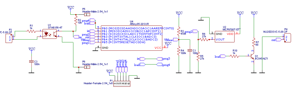
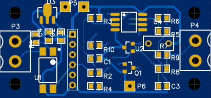
The cell monitors measure both the temperature and the voltage of the cells, they even have a possibility to switch on a small load to balance the cells when one of the cells is loaded faster than the other cells. All cell monitors are calibrated, and the calibration results are stored in EEPROM. It is possible to inject calibration messages in the string of monitors to alter these values.
The power of the cell monitor is delivered by the cell it self, so power reduction was one of the main requirements, when in quiescent state they use 50 µA. And they become active once every minute for a fraction of a second. There is no regulator the ATTiny 85 processor can run on voltages from approximately 2 Volt upto 5 Volt. A resistor of 68 ohm is used for the balancer, so approximately 50 mA will be balanced. Not much, but it will be used rarely, it’s more a matter of just in case, and it was easy to create the option.
Because the ATTiny runs on an RC oscillator and not a crystal oscillator, the timing is less accurate, especially because of the wide range in power supply from the cell. When a normal (e.g. RS232 or NMEA0183) would be used, problems may occur when transmitting a couple of bits with the same polarity in succession. To prevent this I implemented a Manchester encoding, every bit changes its polarity halfway the bit time. A ‘1’ is a zero to one transition, and a ‘0’ is a one to zero transition. (Or the other way around, I’m not sure 🙂 ). The base of the software was the NeoSWSerial library for Arduino, but it is modified to Manchester encoding, and stripped to the last bit to save memory.
The end device is an ATMEGA 328P based Redboard, connected to a Dragino (LoRa) shield, connected to my own ‘shield’ with connectors to the LCD display, the relay to switch the charger, and the connector to the cell monitor. It is also optimized for low power consumption, and uses approximately 3 mA. It runs an image with mainly LoRa software, combined with some software I wrote myself, including the NeoSWSerial-Manchester code.